|
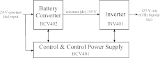
The “inverter” described in this series includes an input-stage battery converter (BCV402) with control support (BCV401). The converter outputs a constant 155 V, the peak of the bipolar waveform generated by the inverter (INV401). (Part 1)
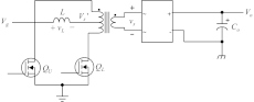
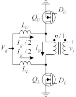
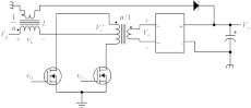
The Volksinverter battery converter BCV402 power-transfer circuit is a boost push-pull (BPP), although this will undergo some refinement later. (Part 11)
This series included analyses of competing topologies such as the interleaved or differential boost push-pull (DBPP) and extended BPP for the power-transfer circuit.
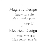
This general design procedure for transductors was used to design the transformers and inductors in the Volksinverter. (Part 15) Special Series on Designing An Open-Source Power Inverter This 25-part series of articles explains the engineering of a kilowatt-level, scalable open-source battery inverter that the author has dubbed the “Volksinverter,” Just as the Volkswagen Beetle was intended to be a car for the people, this inverter is meant to be a product suitable for widespread use. Its key characteristic is the open-source nature of this design. In this article series, the design of the Volksinverter will be described in enough detail that a sufficiently technically savvy owner will be able to maintain, repair, or even modify the design, including the magnetic components. Like Linux, the Volksinverter design will lend itself to discussion by user groups on the Internet who will be able to share ideas, observations, procedures, modifications, corrections and enhancements of it. Anyone will be free to manufacture and sell it, as-is or in modified form. This series was published in the How2Power Today newsletter. Links to all the parts in this series are provided below. If you have comments or questions on any aspects of this series, please share them with the editor. “Designing An Open-Source Power Inverter (Part 1): Goals And Specifications” by Dennis Feucht, How2Power Today, May 2021. Part 2: Waveshape Selection, September 2021. Part 3: Power-Transfer Circuit Options, April 2022. Part 4: The Optimal Power-Line Waveshape, May 2022. Part 5: Kilowatt Inverter Circuit Design, July 2022. Part 6: Kilowatt Inverter Control Circuits, August 2022. Part 7: Kilowatt Inverter Magnetics, September 2022. Part 8: Converter Control Power Supply, November 2022. Part 9: Magnetics For The Converter Control Power Supply, December 2022. Part 10: Converter Protection Circuits, February 2023. Part 11: Minimizing Switch Loss In Low-Input-Resistance Converters, March 2023. Part 12: Sizing The Converter Magnetics, May 2023. Part 13: The Differential Boost Push-Pull Power-Transfer Circuit, June 2023. Part 14: Boost Push-Pull Or Buck Bridge?, July 2023 Part 15: Transformer Magnetic Design For the Battery Converter, March 2024. Part 16: Transformer Winding Design For the Battery Converter—Efficiency Range And Winding Allotment, April 2024. Part 17: Transformer Winding Design For the Battery Converter—Alternative Configurations, May 2024. Part 18: Transformer Winding Design For The Battery Converter—Secondary Winding Design, July 2024. Part 19: Controller Design For The Battery Converter, September 2024. Part 20: Converter Inductor Magnetic Design, October 2024. Part 21: Converter Inductor Winding Design, November 2024. Part 22: Converter Regulator Dynamics, December 2024. Part 23: Inverter Driver Design Refinement, January 2025. Part 24: Inverter Output Filter Conundrum, February 2025. Part 25: Boost Or Buck For Converters That Increase Voltage?, April 2025. To learn more about inverter design, see these articles published by How2Power and other sources.
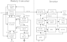
Block diagram of the Battery Converter and Inverter stages.
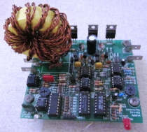
Prototype circuit boards with the allotted magnetic components.
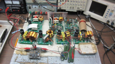
Closeup of a prototype INV401 inverter circuit-board. (Part 5)
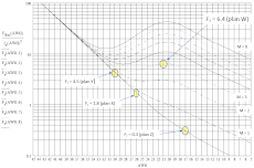
Various plots of Eddy-current resistance ratio based on the Dowell equation are used to determine optimum wire size for magnetic components. (Part 18)
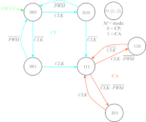
Logic flow diagram of CA-CP PP dual-mode control. (Part 19) |
|
This site is protected by copyright laws under U.S. and international law. All rights reserved.
|