|
As discussed in part 1, higher power dc chargers are typically built in a modular fashion, where power blocks of 15 to 75 kW (and above) are stacked together in a single cabinet. This series describes the design of a 25-kW dc charger module.
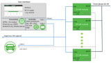
A high-power fast dc charger constructed by stacking several power stages (left). Each of these power stages consists of a PFC stage and a dc-dc converter stage (right). (Part 2)
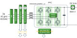
The three-phase six-switch topology, active rectification stage with power factor correction (PFC), also known as the PFC stage. (Part 2)
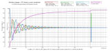
Inrush current protection. Input currents on phases A & B and PFC output voltage at startup with inrush protection activated. (Part 3)
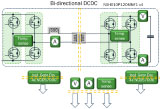
IThe dual active bridge (DAB) dc-dc stage. The system consists of two full-bridges with an isolation transformer in between. (Part 4) Developing A 25-kW SiC-Based Fast DC Charger NEW
The fast dc charging market is thriving. Along with the acceleration in the adoption of electrical vehicles (EVs), the demand for fast charging infrastructure is increasing. Growth projections range from 20% to 30% CAGR for the next five years. If you are an application, product or design engineer working in the power electronics field, sooner or later you could be involved in the design of one such novel charging system. In this article series, which was originally, published in the How2Power Today newsletter, members of ON Semiconductor’s EMEA Systems Engineering team walk through the process of designing and developing a 25-kW fast dc charger based on SiC power integrated modules (PIMs). This 25-kW dc charger module serves as a building block that can be stacked to create a higher power dc-charger system for fast charging EVs. Part 4: Design Considerations And Simulation Of The DC-DC Stage Part 5: Control Algorithms, Modulation Schemes And Feedback Part 6: Gate Drive System For Power Modules Part 7: Auxiliary Power Supply Units For 800-V EV Chargers
To learn more about battery charger design, see the How2Power Design Guide, locate the “Power Supply Function” category and select “Battery chargers”.
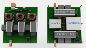
The PFC stage with fan assemblies attached to PIMs and blowing towards PFC chokes (left) and the dc-dc converter stage with fan assemblies attached to primary and secondary PIMs (right). (Part 8)
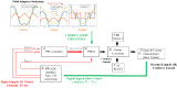
High-level block diagram of the PFC control algorithm. (Part 5)
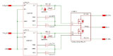
Power stage with gate driver model for PFC phase A. (Part 6)
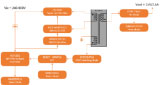
An auxiliary PSU is used to power the controllers, drivers, communications components, and sensors of the submodules, while taking its input power from the dc link voltage. (Part 7)
Since 2009, HOW2POWER has published hundreds of detailed technical articles on power supply design in our monthly HOW2POWER TODAY e-newsletter. Click here to subscribe to this free newsletter. |


|
This site is protected by copyright laws under U.S. and international law. All rights reserved.
|