|
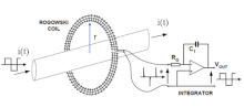
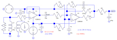
The Rogowski coil wires are connected to an integrator that compensates for the differentiating property of the mutual inductance between the bus carrying current i(t) and the coil placed at a distance r from the bus. Diagram courtesy of Keysight. (Part 1)
The Rogowski coil schematic.
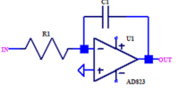
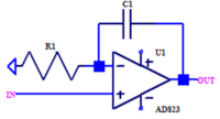
Inverting (top) vs non-inverting (bottom) integrator. (Non-Inverting Integrator series, parts 1 and 2) Designing Rogowski Sensors: Two Special Article Series On Sensor And Integrator Design As the author explains in launching his article series on Rokowski sensors design, “Current measurement is a common requirement in many power converter and inverter designs. Traction inverters are just one example. Rogowski sensors are an interesting option in this case as they have a very wide current range, very high accuracy (up to 0.1%), and are non-saturating. On the down side, they are very expensive, costing as much as $3000 for an instrument-grade sensor. However, in cases such as a traction inverter, the full accuracy of an off-the shelf Rogowski coil sensor may not be needed. In this case, it may be possible to design and build a lower-cost sensor that retains most of the benefits of this current-measuring sensor. To that end, I have developed, calculated and simulated a prototype of a Rogowski current sensor that can be much less expensive than the existing ones but still have very good accuracy. Implementing this sensor design depends mainly on an understanding of Rogowski coil operation and having the key formulas available for designing the coil and the integrator circuit. The author offers an introduction to designing Rogowski in a three-part series published in the How2Power Today newsletter where he derives the formulas defining the operation of the Rogowski coil (part 1), explains details of the associated integrator design (part 2) and presents simulations of the final sensor design (part 3). He then goes into greater detail on various aspects of integrator design — much of which is relevant to Rogowski sensor design — in a second set of articles published in How2Power Today. Links for all of these articles are provided below with issue dates noted. “A Guide To Designing Your Own Rogowski Sensor (Part 1),” April 2024. “A Guide To Designing Your Own Rogowski Sensor (Part 2),” May 2024. “A Guide To Designing Your Own Rogowski Sensor (Part 3),” June 2024. “Non-Inverting Integrators Are Not Really Integrators (Part 1),” May 2025. “Non-Inverting Integrators Are Not Really Integrators (Part 2),” June 2025. “Non-Inverting Integrators Are Not Really Integrators (Part 3): Impact On Rogowski Sensors,” July 2025. “Controlling Rogowski Sensor Frequency Response Through Integrator Design,” October 2025. “Integrator Feedback Resistor—Adverse Or Friendly? How To DC Stabilize An Integrator Output,” November 2025. “Average Value Extractor Is More Precise Than Low Pass Filters,” December 2025. For more articles by the author on other topics in power supply, magnetics and analog circuit design, see Gregory Mirsky’s Special Contributor page.
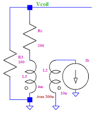
Schematic of the simulated Rogowski sensor. (Part 3)
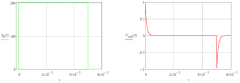
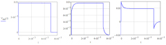
Demonstration of the trapezoidal current waveform to measure and voltage generated by the Rogowski coil. (Part 2)
The integrator output voltage at different values of correction resistor. (Part 2)
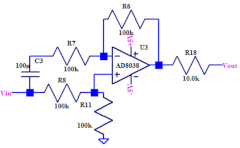
A high-frequency differential amplifier used to build an average value extractor to dc stabilize the integrator. (Average Value Extractor article) |
|
This site is protected by copyright laws under U.S. and international law. All rights reserved.
|